Ide 37+ 24V Inverter Circuit Diagram
Ide 37+ 24V Inverter Circuit Diagram. Dalam dunia skema amplifier mungkin Anda pernah mendengar dengan yang namanya kumpulan skema amplifier. Komponen dasar skema amplifier beserta fungsi dan simbolnya yang harus kamu ketahui, Simak ulasan terkait skema amplifier dengan artikel Ide 37+ 24V Inverter Circuit Diagram berikut ini

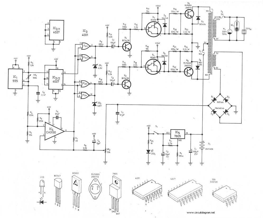
12v To 24vdc Inverter Schematic Circuit Diagram Images Sumber : circuitdiagramimages.blogspot.com

Inverter 12V 24V 48V 3000 Watts 3kW Pure Sine Wave DC to Sumber : www.electriccarpartscompany.com

how to build a 2KVA inverter circuit diagram 2000 watt Sumber : everproject.blogspot.com

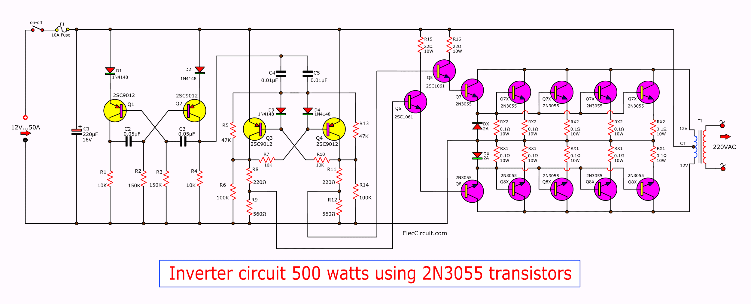
24v to 220v inverter circuit 300W power ElecCircuit com Sumber : www.eleccircuit.com

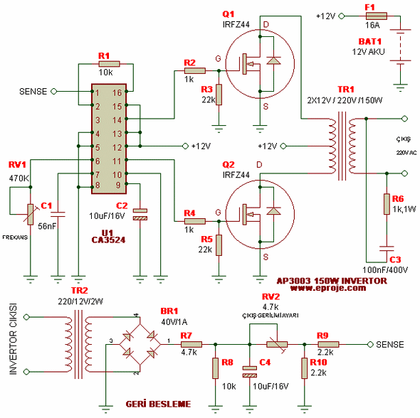
250W 5000W SG3524 DC AC Inverter Circuit Electronics Sumber : 320volt.com

Digital Modified Sine Wave Inverter Circuit 250 watts Sumber : circuitdiagramcentre.blogspot.com

Inverter 5000W with PWM Pulse Width Modulator Sumber : rangkaianlo.blogspot.com

500W DC to AC Inverter with FET IRFP260 Inverter Circuit Sumber : inverter-circuit.com

I m Yahica 300w Inverter Circuit Diagram Sumber : codecwired.blogspot.com

Circuit Zone com Electronic Projects Electronic Sumber : circuit-zone.com

12V 24V 48V 2000W 2KW 120V 230VAC 50Hz 60Hz Output Pure Sumber : electriccarpartscompany.com

I m Yahica 24v Inverter Circuit Diagram Sumber : codecwired.blogspot.com

inverter fahriemjeblog Sumber : fahriemjeblog.wordpress.com

Super Circuit Diagram 24V to 12V 400W DC Inverter Circuit Sumber : circuitsan.blogspot.com.au

300Watt Inverter DC 24V to AC 220V Circuit Scheme Sumber : circuitscheme.com

12v To 24vdc Inverter Schematic Circuit Diagram Images Sumber : circuitdiagramimages.blogspot.com
7 Simple Inverter Circuits you can Build at Home
Inverter 12V 24V 48V 3000 Watts 3kW Pure Sine Wave DC to Sumber : www.electriccarpartscompany.com
24V To 12V Converter Circuit Diagram
Many times we have the requirements of 24V to 12V converter The circuits shown below can be used to convert 24V DC to 12V DC These type of circuits are also called DC to DC converters You can step down 24V DC to 12V with the help of voltage regulators ICs The circuit shown in figure 1 is using

how to build a 2KVA inverter circuit diagram 2000 watt Sumber : everproject.blogspot.com
24V Battery Charger Schematic Instructables
Hello Maxolous please can you send to my mail a circuit diagram of how to incorporate this 24 volt battery charger you design into your inverter circuit diagram to be able to use the inverter transformer to 24v 0 24v tapping to charge the 24volts battery my mail is

24v to 220v inverter circuit 300W power ElecCircuit com Sumber : www.eleccircuit.com
3000 Watt Inverter Circuit Diagram Electronic Circuit

250W 5000W SG3524 DC AC Inverter Circuit Electronics Sumber : 320volt.com
300Watt Inverter DC 24V to AC 220V Schematic Design
This is the 300W inverter circuit which capable to convert 24VDC become 220VAC With this circuit you will have 220V AC power with 300W max rated from 24V lead acid battery or accumulator Schematic diagram PCB layout and component placement Since this circuit has lethal potential and high risk please be careful when try this circuit

Digital Modified Sine Wave Inverter Circuit 250 watts Sumber : circuitdiagramcentre.blogspot.com
Basic Inverter Electronic Schematic Diagram
The following diagram is the basic design diagram of inverter circuit The circuit will convert 12V DC to 120V AC This basic inverter circuit can handle up to 1000Watts supply depends the T1 T2 and transformer used Please see the note Basic Inverter Components list Part Total Qty

Inverter 5000W with PWM Pulse Width Modulator Sumber : rangkaianlo.blogspot.com
2000w inverter circuit diagram High power inverter circuit
1 15 2021 2000W Inverter circuit diagram This is the circuit diagram of 2000w high power inverter circuit This is based on the mosfet3205 use 24v DC supply for operation and connect 24v 5A or more than 5A transformer Please careful with this circuit because high A
500W DC to AC Inverter with FET IRFP260 Inverter Circuit Sumber : inverter-circuit.com
Wiring Diagram of Solar Panel with Battery Inverter
9 1 2021 This inverter circuit diagram which can change the voltage 12 Volt DC to 230 Volt AC Scheme inverter circuit is capable of removing power output up to 3000 Watt for beginners as possible to assemble a circuit schematic This inverter will be a little complicated and confused but if it succeeds in assembling or assemble it certainly results will be comparable to what we have done and
I m Yahica 300w Inverter Circuit Diagram Sumber : codecwired.blogspot.com
6 Best Simple Inverter Circuit Diagrams DIY
3 Phase Inverter Circuit Diagram The internet is flooded with single phase inverter circuit diagrams but there are only few circuit diagrams of 3 phase inverter out there a simplest possible 3 phase inverter is described here Three phase inverters require microcontroller design where the timings of the all three phases need to be precisely
Circuit Zone com Electronic Projects Electronic Sumber : circuit-zone.com
Homemade 2000w power inverter with circuit diagrams GoHz com
10 8 2021 Few days ago GoHz made a 24V 2000W power inverter in home sharing some design schematics and circuit diagrams Power inverter testing The picture was taken in short circuited Output waveform The SPWM accuracy of EG8010 was not high enough waveform so the inverter output was not good enough as pure sine wave The dead zone time was a bit
12V 24V 48V 2000W 2KW 120V 230VAC 50Hz 60Hz Output Pure Sumber : electriccarpartscompany.com

I m Yahica 24v Inverter Circuit Diagram Sumber : codecwired.blogspot.com

inverter fahriemjeblog Sumber : fahriemjeblog.wordpress.com

Super Circuit Diagram 24V to 12V 400W DC Inverter Circuit Sumber : circuitsan.blogspot.com.au

300Watt Inverter DC 24V to AC 220V Circuit Scheme Sumber : circuitscheme.com


0 Comments